This looks really good Stewart, I’ve been playing with it this evening on an iPad which obviously makes some tasks difficult. Nonetheless the resulting gcode looks good and hope to try on my X-Carve this weekend.
Is there a way to increase “scale” in just the Z axis. I.e. import a land terrain STL and make it taller while keeping X and Y as was?
Laser slicer looks interesting too, look forward to trying that.
Thanks, Ian. If you hover over any field (which I know isn’t possible on an iPad) it will provide extra info. For scale, it will accept a single # or a comma separated list (width, depth, height). So you can scale just Z with “1,1,0.5” for example, when an object is selected (must be green).
I milled something last night that is similar to what you’re doing. I used a 1/8" end-mill with only roughing and x/y finishing with “cutout tabs” enabled.
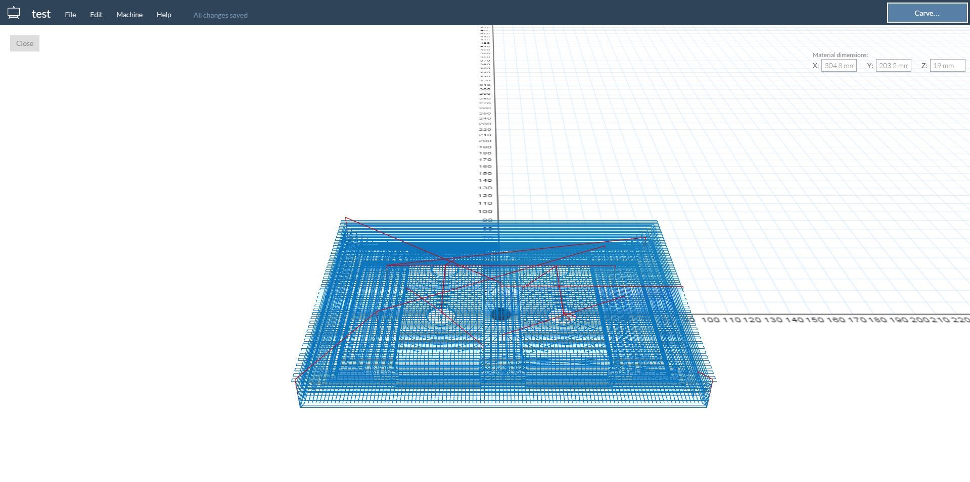
… I’ve tried saving the g-code file and importing it Easel, but the placement just seems wierd, it’s not placing the entire object on the worktable (see attached image).
If you uncheck “origin center” under “output” on the right, the origin becomes bottom left of the “platform” (as defined under the “device” menu on the right). You can the treat the platform as the stock and size appropriately … or move your object on the platform to the bottom left.
@StewartAllen I’m having trouble accurately positioning an item to the bed for the bottom left corner for CAM usage. Is there a way I haven’t found yet?
Origin at centre is fine for 3D printing but while matching a design to stock for X-carving I need to really get the design square to bottom left corner.
@IanWatkins, under “device” on the right, set the “bed width” and “bed depth” to the size of your stock. That in combination with unchecking “origin center” should allow you to set 0,0 to the bottom left of your stock (if you leave the part center on the bed with auto-arrange). Will that work for you?
@TonyNo definitely seems like a small delta from what I’m already doing. In fact, it’s basically what laser mode does but outputting gcode instead of DXF/SVG … check that out and see if that’s true. If so, I can make some quick changes to have laser mode also emit GCode.
I tried that and it’s close. But look at it another way, I have two items to carve in my design and need to absolutely position them exactly say 40mm apart. At the moment it looks as though I have to do it by eye?
@IanWatkins … I see. Ok, I added an option for direct position control. Select an object then type ‘P’ (uppercase P) and a dialog will pop up. You can type in X,Y coordinates to precisely position your selection. In your case, you will need to make sure ‘origin center’ is unchecked. I’ll improve this feature in the future. But it should get you going.
@StewartAllen Thank you Stewart, that is very helpful and works just fine. That’s good enough for me
One final question before I commit tool to material…
I’m just doing a roughing pass at the moment and set feed rate to 2400 (I’m doing carvable wax) and plunge rate to 400 (X-Carve is 500 mm/min max in my config).
But when I look in the resulting gcode I’m seeing Z move requests faster than F400.
I’ve had similar issues with MeshCam jobs travelling fast in the X-Y but not being able to keep up in the Z because of the different rate it travels. Guess I’m just looking for some reassurance here.
@IanWatkins that looks wrong. The only way Z axis travel should exceed plunge rate is in combination with an ease-down (which means it’s also traveling along the X/Y axis). Let me go check the code.
@IanWatkins I pushed a change that may fix this. please reload and try again. If you go to the help menu, it should say “version 1.0.15g” at the bottom.